Robot Arm Kinematics: From Joint Angles to Position
How a robot arm turns joint angles into a hand position. Forward kinematics with sines and cosines, reach limits, and why targets can have two answers.
A robot arm is a chain of rigid links joined by motors. Tell each motor how far to turn and the hand ends up somewhere specific in space. Working out where is called forward kinematics, and it needs nothing more than right-angled triangles. This guide walks through it for a simple three-joint arm.
Joints, links and the tool point
Strip a robot arm down and you find two kinds of part:
- Joints, which rotate (or sometimes slide) and are driven by motors.
- Links, the stiff segments between joints, which never change length.
At the free end sits the tool point, the spot where a gripper, pen or welding head would be. The question forward kinematics answers is simple: given every joint angle, where is the tool point?
The reverse question, finding joint angles that reach a chosen point, is called inverse kinematics. It is harder, and we come back to it near the end. Start with the forward direction, because it is pure geometry with one answer every time.
A flat two-link arm with a bit of trigonometry
Look first at two links moving in a single flat plane. Call the link lengths L1 and L2. The shoulder angle θ1 is measured from the horizontal, and the elbow angle θ2 is measured relative to the first link, not to the ground.
The tool position follows from adding two vectors, one per link:
x = L1 cos θ1 + L2 cos(θ1 + θ2)
y = L1 sin θ1 + L2 sin(θ1 + θ2)
The first term in each line is where the elbow sits. The second term is the extra offset from elbow to tool. Notice that the second link points in the direction θ1 + θ2, because the elbow angle is measured from the first link. Forgetting that addition is the most common slip.
Because every link is rigid, nothing else matters. Give the same angles twice and you always get the same point.
Yaw: turning the whole plane
Real arms are not confined to a plane. A base joint, called yaw, rotates the whole arm about the vertical axis. Think of a desk lamp swivelling on its base.
Yaw leaves two things untouched: the length of each link and the height of the tool above the base. All it does is spin the working plane, so the horizontal reach gets pointed in a new direction. If the flat arm reaches a distance r out from the base, then a yaw of ψ places the tool at
horizontal position = (r cos ψ, r sin ψ)
while the height stays as before. That splits a three-dimensional problem into a two-dimensional arm problem plus a rotation, which is why many industrial arms are built this way.
How far can the arm reach?
The arm’s reach is bounded by its links. The farthest the tool can get from the shoulder is when both links line up straight: L1 + L2. For links of 1.65 m and 1.25 m, that is 2.90 m.
The nearest it can get is when the elbow folds all the way back: |L1 − L2|, here 0.40 m. In between, the tool can reach a ring-shaped region around the shoulder. Anything outside that ring is simply out of reach, however clever the controller.
This workspace is one of the first things engineers check when choosing an arm. A target that looks close to the base might still be unreachable if it falls inside the inner circle.
Why one target can have two answers, or none
Run the maths backwards and something interesting happens. Pick a reachable point and there are usually two ways to get there: the elbow can bend one way (often called elbow up) or the other (elbow down). Both put the tool in exactly the same place.
There are three cases:
- Two solutions, when the point lies strictly inside the reachable ring.
- One solution, when it sits right on the edge, with the arm fully stretched or fully folded.
- No solution, when it lies outside the ring.
That is why inverse kinematics is trickier than forward. The forward direction always gives one answer. The reverse direction can give two, one or none, and the controller has to choose between them sensibly, for example by avoiding a collision with the table.
Common misconceptions
- "The elbow angle is measured from the ground." In this convention it is relative to the first link, so the second link’s direction is the sum of both angles.
- "Bigger joint angles always mean bigger reach." Reach depends on how straight the arm is, not on how much it has turned.
- "If a point is close, it is reachable." Inside the minimum reach circle it is not.
- "Yaw changes the height." It does not; it only rotates the arm about the vertical.
How to explore this in the lab
The Robot Arm Lab gives you sliders for yaw, shoulder and elbow and shows the tool point moving in 3D. The free first world has two lessons, and they fit this guide in order:
- The robot’s coordinate system sets up the axes, the angle conventions and the two link lengths, and lets you find the arm’s maximum reach.
- Turn a plane through space shows what the base joint does and does not change.
After those, try to hit a target by hand and notice how often a second arm pose also works. Later worlds in the lab extend this to solving target positions directly.
The lab is a simplified teaching model: perfectly rigid links, no motor limits, no gravity sag. Real robots add all of those, but the geometry you learn here is the core.
- Forward kinematics adds one vector per link: each link points along the sum of the joint angles before it.
- The elbow angle is relative to the previous link, not to the ground.
- Yaw spins the arm’s plane without changing link lengths or tool height.
- Reach runs from |L1 − L2| to L1 + L2; targets outside that ring are impossible.
- Going backwards from a point to joint angles can give two answers, one, or none.
The robot’s coordinate system
About 8 minutes. Free, no account, runs in your browser.
More free lessons from this guide
Simulations on Novareka are teaching models, simplified on purpose. They show how an idea behaves; they are not a substitute for professional, medical or engineering advice.
Labs in this guide
 Live
Live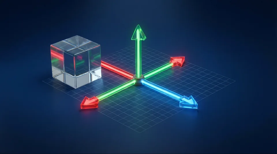 Live
Live Live
LiveKeep reading
All guides → Explainer
 Explainer
 Explainer