Ohm’s Law Explained: Voltage, Current and LED Resistors
Learn what voltage, current and resistance mean, how Ohm’s law links them, and how to pick the resistor that protects an LED. Includes a live 3D circuit lab.
Almost every circuit, from a torch to a phone charger, comes down to three quantities: voltage, current and resistance. One short equation ties them together, and it also tells you why an LED needs a small resistor beside it. This guide builds that picture step by step, using small battery-powered circuits only.
Three quantities that describe every circuit
Electric charge moving through a conductor is called current. Something has to make it move, and that something is voltage. Something also gets in the way, and that is resistance.
- Voltage (V), measured in volts, is the energy given to each unit of charge as it crosses a source such as a battery. It is the push.
- Current (I), measured in amperes (amps), is how much charge passes a point each second. It is the flow.
- Resistance (R), measured in ohms (Ω), tells you how strongly a part opposes that flow.
A water analogy helps at first: voltage is like pressure, current is like the flow rate through a pipe, and resistance is like a narrow section of pipe. Like every analogy it has limits, but it gives the right feel for how the three depend on each other.
A word on safety scope: everything here is about low-voltage, battery-sized circuits. Household mains electricity is dangerous and is not something to experiment with, so this guide and the lab never go there.
Ohm’s law: one equation, three answers
For many ordinary resistors, doubling the voltage across them doubles the current through them. That straight-line relationship is Ohm’s law:
V = I × R
Rearranged, it answers three different questions:
- Need the voltage?
V = I × R - Need the current?
I = V / R - Need the resistance?
R = V / I
A quick example: a 9 V battery across a 450 Ω resistor gives I = 9 / 450 = 0.02 A, which is 20 milliamps. Change any one of the three numbers and the others follow.
Ohm’s law describes a particular kind of part, called an ohmic resistor, at roughly constant conditions. Some components do not obey it, and one of them is the LED, which we meet in a moment.
Reading the numbers: milliamps, kilohms and colour bands
Real circuits use prefixes constantly. 1 mA is a thousandth of an amp. 1 kΩ is a thousand ohms. Mixing units is the commonest slip when using V = I × R, so convert first: 20 mA becomes 0.02 A before you divide.
Small resistors carry a row of painted bands instead of printed numbers. In the common four-band style, the first two bands are digits, the third is a multiplier and the fourth is the tolerance, which tells you how far the true value may stray. Brown, black, red, for example, reads as 1, 0, then ×100, which is 1 kΩ.
You do not need to memorise the whole code on day one. Reading a few resistors in the lab until the pattern clicks works better than a table.
Why an LED cannot be wired straight to a battery
A normal resistor lets current rise smoothly as voltage rises. An LED (light-emitting diode) does not. Below a certain voltage, called its forward voltage, it passes almost nothing. Just above that voltage, the current climbs very steeply for a tiny extra push.
That makes a bare LED on a battery a gamble: the battery pushes on, the current grows far beyond what the LED is built for, and the LED can fail almost at once. The LED has no built-in way to say "enough".
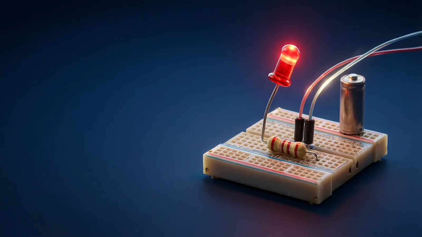
The fix is to add a current-limiting resistor in series. Because the same current must flow through both parts, the resistor takes the voltage the LED does not need and, through Ohm’s law, caps the current.
Choosing the resistor: a worked example
Suppose a red LED has a forward voltage of about 2 V and you want roughly 15 mA through it, powered from a 5 V supply.
- Find the voltage left over for the resistor:
5 V − 2 V = 3 V. - Divide by the current you want:
R = 3 / 0.015 = 200 Ω. - Pick the nearest standard value that is not smaller, such as 220 Ω. The current ends up slightly lower and the LED a little dimmer, which is a safe direction to err.
We can also ask how much power the resistor handles. Power is P = V × I, so 3 V × 0.015 A = 0.045 W, comfortably within the rating of a small resistor.
Always check the LED’s own data for its forward voltage and recommended current; the figures above are typical, not universal.
Mistakes to avoid
- Forgetting to convert units. Milliamps and kilohms need turning into amps and ohms before dividing.
- Putting the resistor in parallel. For the current limit to work, the resistor must be in series, in the same loop as the LED.
- Reversing the LED. An LED only conducts one way. If it stays dark, try flipping it before blaming the maths.
- Treating Ohm’s law as universal. It applies to resistors, not to every part in the circuit.
- Thinking "less resistance is safer". The opposite is true for an LED: a smaller resistor lets more current through.
How to explore this in the lab
The Electronics & Arduino lab lets you build and measure these circuits without hardware. A sensible order through the free first world:
- Start with Voltage, Current, Resistance to separate the three ideas.
- Test the equation in Ohm’s Law in practice, then practise the three rearrangements in Rearranging Ohm’s Law.
- Look at how an LED behaves in The LED.
- Protect it with Current-limiting resistors.
- Finish with Power & watts to see how much heat the resistor handles.
The lab is a simplified teaching model of ideal parts, so real components will differ a little in the details. Stick to low-voltage batteries and USB-level supplies for your own experiments.
- Voltage pushes, current flows, resistance opposes: V = I × R ties them together.
- Convert milliamps and kilohms to amps and ohms before you calculate.
- An LED needs a series resistor because its current rises steeply above its forward voltage.
- Resistor value = (supply voltage − LED voltage) ÷ wanted current, rounded up to a standard value.
- Keep home experiments to low-voltage batteries; never mains electricity.
Voltage, Current, Resistance
The three core quantities. About 7 minutes. Free, no account, runs in your browser.
More free lessons from this guide
Simulations on Novareka are teaching models, simplified on purpose. They show how an idea behaves; they are not a substitute for professional, medical or engineering advice.
Labs in this guide
 Live
Live Live
Live Live
LiveKeep reading
All guides → Explainer
 Explainer
 Explainer